Choosing the number of stages during the development of axial turbines is one of the most controversial design tasks because it has many options to consider. This task does not have an exact solution, since it depends on the total turbine work, circumferential velocity and is determined by a combination of gas-dynamic, strength, construction, and technological factors. This blog will discuss some of the considerations for stage number selection of an axial turbine.
Using Stage Loading vs Parson’s Parameter
Designing turbines requires the use of complex parameters to simultaneously consider the influence of various factors on the characteristics of the turbine. Thus, the stage loading (mostly aircraft turbines) or the Parson’s parameter (stationary turbines and aircraft turbines) have been used for wide applications in turbines theory.
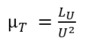
- Stage loading is the ratio of the theoretical turbine work LU and the square of the circumferential velocity U.
- Parson’s parameter y is the ratio of the circumferential speed to the speed equivalent to the isentropic heat drop.
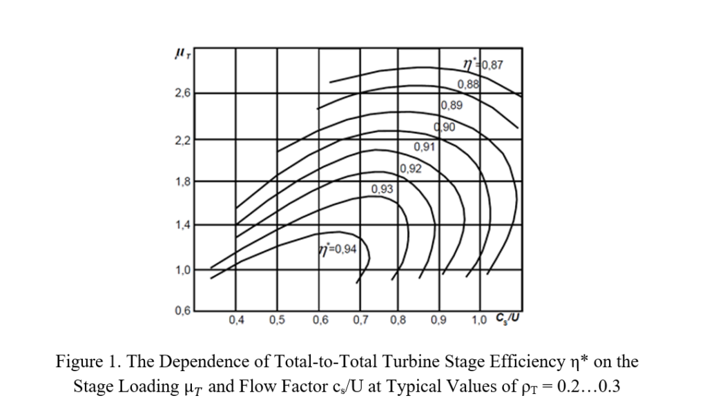
High turbine efficiency is achieved, when these parameters are in the range μT = 1.2…1.6 (y=0.45…0.6), which can be seen in Figures 1 and 2 [1], respectively.


Using these parameters, the number of stages ZT (or U) can be determined approximately by conditionally considering a multistage turbine with the same circumferential velocity and theoretical work in all stages. Then the expression for the average value of the stage’s loading is:

Parson’s parameter can also be used to estimate the average stage loading. That formula is:

In aircraft turbines, these values are higher than optimal, which happens with a reduction in the weight and the overall dimensions of the turbine and engine. So, for a high-pressure turbine (HPT), the values μT ≤ 2 are typical, and for a low-pressure turbine (LPT) the value is μT ≤ 2,2. A further increase in μT is impractical not only because of the decrease in efficiency (Figure 1), but also because an increase in μT ≥ 2 … 2.1 does not lead to a reduction in the mass of the turbine, although it does give some reduction in the tip diameter (3…4%) [2].
The first stages of high-temperature aircraft turbines need to be cooled, which imposes additional technological, design and strength restrictions on the stage loading( μT ≤ 1,8), then, in turn, affects the choice of the number of stages. The blades of the cooled turbine with a (μT ≥ 1,8) are significantly twisted, which makes it difficult to manufacture channels for supplying cooled air inside them. In addition, the blades have strength problems caused by high speeds and temperatures, and for a μT ≥ 1,8 they only increase. On the other hand, the presence of the cooling air supply system complicates the layout of the turbine, which also affects the choice of the number of stages.
High-Pressure Turbines (HTPs) vs Low-Pressure Turbines (LPTs) in Stage Count
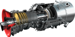
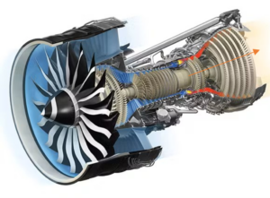
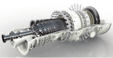
As a rule, two-shaft or three-shaft turbofans are the most common engines in aviation. The modules of HPTs or middle-pressure turbines (MPT) are generally one or two stages (Figures 3&4). At the same time, the heat drop maxes out in the first stages (HPT and MPT), improving the temperature regime of subsequent stages.

![Figure 4. Rolls-Royce Trent 900 [4]](https://platoaistream.com/wp-content/uploads/2022/12/stage-number-selection-in-axial-aircraft-turbines.jpg)

Ensuring the axial flow outlet angle is achieved by reducing the work from the last turbine stage of the module can also affect the choice of the number of turbine stages, (skewing towards a larger number). In addition, more turbine stages can be desirable to avoid increases in aerodynamic losses.
Figure 6 shows a typical distribution of the stage loading in a three-module aircraft turbine.

While figure 6 shows the load distribution over the stages at design mode, this distribution can change significantly during off-design operation. In particular, the heat drop in the last stages of the turbine is redistributed during off-design turbine modes. This should be considered when choosing the design distribution of the heat drop, the outlet speed and the outlet angle of the turbine.
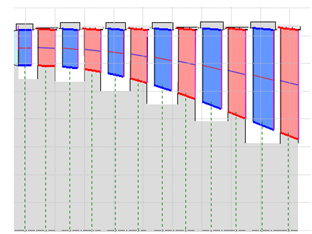
Another factor affecting the number of turbine stages is the shape of its flow path. For instance, the flow path with Dtip = const (Figure 7), with other advantages and disadvantages [2], enables the obtainment of the highest value of circumferential velocities at all stages, which can be used to reduce the number of stages or to increase the loading.
As we can see from the above, choosing the number of stages in axial turbines is a complex optimization task, which is solved with the help of engineering software tools using mathematical methods. One such software is AxSTREAM, and its generative design module can be particularly helpful as seen in the next example.
Figure 8 shows the dependence of the total-to-total turbine efficiency, tip diameter and blade weight of an aircraft’s axial gas turbine (fan turbine of a turbofan engine) on the number of stages at a given rotation speed, gas flow rate, inlet temperature and pressures at the inlet and outlet of the turbine.

Based on the dependence shown in Figure 8 (or dependence of a similar type), an analysis is carried out, and a decision can be made on the ideal number of stages earlier on in the design process accounting for various restrictions.
Choosing the number of stages is a complex optimization task, limited by not only high-efficiency requirements, but also on constraints around construction, technology, strength, and layout. Luckily these days we have software to help us along the way and save us from manual number-crunching. If you’re interested in exploring how AxSTREAM can help you with your next gas turbine design project, get in touch by emailing us at Info@Softinway.com.
References
- Kholshchevnikov, K.V., Emin, O. N., Mitrokhin, V. T. Teoriya i raschet aviatsionnykh lopatochnykh mashin [Theory and Design of Aircraft Turbomachinery]. Moscow, Mechanical Publ., 1986. 432 p.
- Kopelev, S. Z. Proyektirovaniye protochnoy chasti turbin aviatsionnykh dvigateley [Designing the flow path of aircraft engine turbines]. Moscow, Mechanical Publ., 1984. 224 p.
- Shustov, I.G. Dvigateli 1944-2000: Aviatsionnye, raketnye, morskie, promyshlennye [Engines 1944-2000: Aircraft, rocket, marine, industrial.]. Tekhniko-ekonomicheskaya baza dannykh. Entsiklopediya po dvigatelyam. Vol. 1.
- Doroshko, S.M., Glazkov,S. Gazoturbinnyye Dvigateli Grazhdanskoy Aviatsii [Gas Turbine Engines of Civil Aviation]. St. Petersburg, 2018. 228 p.
- SEO Powered Content & PR Distribution. Get Amplified Today.
- Platoblockchain. Web3 Metaverse Intelligence. Knowledge Amplified. Access Here.
- Source: https://blog.softinway.com/stage-number-selection-in-axial-aircraft-turbines/
- 1
- 2018
- 7
- a
- above
- Accounting
- achieved
- addition
- Additional
- advantages
- affect
- affecting
- AIR
- aircraft
- All
- Although
- analysis
- and
- applications
- approximately
- around
- average
- aviation
- because
- BLADE
- Blog
- caused
- change
- channels
- characteristics
- choice
- choosing
- Close
- COM
- combination
- Common
- complex
- Consider
- considerations
- considered
- considering
- constant
- constraints
- construction
- controversial
- data
- Days
- decision
- decrease
- dependence
- depends
- Design
- design process
- designing
- determined
- Development
- difficult
- dimensions
- direction
- discuss
- distribution
- Drop
- during
- Earlier
- efficiency
- enables
- Engine
- Engineering
- Engines
- Equivalent
- estimate
- Ether (ETH)
- example
- Exploring
- factors
- fan
- Figure
- Figures
- First
- flow
- formula
- from
- further
- GAS
- generally
- generative
- get
- Give
- given
- happens
- help
- helpful
- High
- higher
- highest
- How
- HTTPS
- ideal
- improving
- in
- Increase
- Increases
- industrial
- influence
- instance
- interested
- IT
- larger
- Last
- Layout
- lead
- Limited
- load
- loading
- loss
- losses
- LPT
- made
- MAKES
- manual
- many
- Mass
- mathematical
- max-width
- mechanical
- methods
- Mode
- module
- Modules
- more
- Moscow
- most
- necessary
- Need
- next
- number
- ONE
- operation
- optimal
- optimization
- Options
- Other
- overall
- parameter
- parameters
- particular
- particularly
- path
- PETERSBURG
- plato
- Plato Data Intelligence
- PlatoData
- PO
- presence
- pressure
- problems
- process
- project
- provide
- put
- range
- Rate
- ratio
- recovery
- reduce
- reducing
- regime
- Requirements
- requires
- restrictions
- Rolls-Royce
- Rule
- same
- Save
- Section
- selection
- Shape
- should
- shown
- Shows
- significantly
- similar
- simultaneously
- since
- So
- Software
- solution
- some
- speed
- speeds
- square
- Stage
- stages
- strength
- subsequent
- such
- supply
- supplying
- system
- Task
- tasks
- technological
- Technology
- The
- theoretical
- time
- tip
- to
- tools
- Total
- touch
- towards
- TURN
- typical
- us
- use
- value
- Values
- various
- VeloCity
- weight
- which
- wide
- will
- Work
- Your
- zephyrnet