The open Brayton cycle is commonly used in gas turbine engines for power generation, aircraft propulsion, and industrial processes. The Brayton cycle, named after American engineer George Brayton, who proposed it in 1872, converts fuel energy into mechanical work. The Brayton cycle became widely used in practical applications following the development of the gas turbine in the 1930s. Gas turbines were used extensively during World War II, and their efficiency and reliability improved significantly.
The Brayton cycle has numerous advantages for energy applications. For one, engineers can design it compactly, making it a strong fit for tight enclosures. With gas turbines being a common engine driver, the Brayton cycle is popular in modern applications. Since Brayton cycle engines are particularly efficient in gas turbine engines, they are useful for power generation, aircraft and marine propulsion, industrial processes, and more.
Additionally, Brayton cycle motors produce few emissions thanks to their efficient exhaust gas treatment systems, making them a greener choice than other fossil fuel systems. Coupled with their high efficiency from the isentropic compression and expansion processes that minimize energy loss, engineers continue to develop Brayton thermodynamic cycle systems to this day.
There are two main types of a Brayton cycle: open and closed. In an open Brayton cycle, the working fluid is continuously supplied to and exhausted from the system, and the process operates in an open loop. On the other hand, in a closed Brayton cycle, the working fluid is contained within the system and circulates in a closed loop. The schematics of a simple open-cycle gas turbine utilizing an internal-combustion process and a simple closed-cycle gas turbine using heat transfer processes are both shown in figure 1.

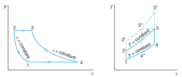
An ideal Brayton cycle consists of the following four processes:
- Isentropic compression: air is compressed to high pressure and temperature via an isentropic process that is adiabatic and reversible.
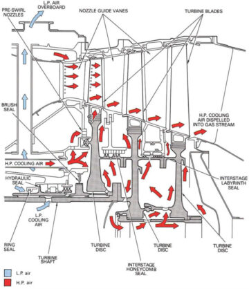
- Constant pressure heat addition: high-pressure air is fed into a combustion chamber where fuel is added and ignited.
- Isentropic expansion: high-temperature gases from the combustion chamber expand in the turbine in an isentropic process, producing mechanical work.
- Constant pressure heat rejection: the exhaust gases are expelled into the atmosphere.
The Brayton cycle is widely studied and used in engineering applications. It remains an important area of research for improving energy efficiency, reducing emissions, and developing new energy generation systems. In addition to the simple Brayton cycle (shown above), which consists of a compressor, combustion chamber, and a turbine and is typically used for power generation, there are different configurations of the Brayton cycle depending on specific applications and performance requirements. Some of these configurations are intercooling, reheating, and regeneration in the Brayton cycle. For instance, the Brayton cycle with a regenerator introduces a heat exchanger to preheat the compressed air before it enters the combustion chamber, reducing fuel consumption and increasing the efficiency of the cycle. The air-standard refrigeration cycle, also known as the reverse Brayton cycle, uses mechanical energy to move heat from a lower temperature source to a higher temperature sink, achieving refrigeration. It is commonly used in the liquefaction of air and other gases, such as in cryogenic refrigerators and air liquefaction plants.

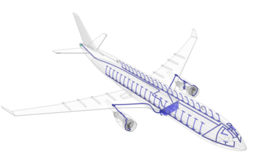
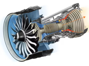
A jet engine (shown in figure 3) is often modeled as operating on an open Brayton cycle. In this cycle, the turbine’s work is sufficient to drive the compressor. In other words, all the work the turbine delivers goes into moving the compressor. The exhaust pressure of the turbine will then be greater than that of the surroundings, and the gas can be expanded in a nozzle. The high velocity of the gases leaving the nozzle is converted into thrust.
The simulation of the gas turbine engine cycle will be demonstrated using AxSTREAM System Simulation by providing a brief overview of some of the features and capabilities of the platform. The simulation process consists of several stages: selecting the working fluids and the components needed to create the model, connecting the parts to form the cycle flow diagram, and assigning boundary conditions and initial approximations before performing cycle initialization, validation, and calculation. The library of materials in the software allows the user to choose materials from various categories, including ideal gases, incompressible liquids, solid materials, perfect thermal mixtures, CoolProp, etc. For our gas turbine engine cycle, Simple Air (oxidizer), FLUEGAS (exhaust gas), and n-Octane (fuel) are selected. Next, the gas turbine engine cycle components are selected from the Cycle library of elements which offers a large selection of cycle components, including turbomachines, heat exchangers, electrical power equipment, separators and mixers, and many more. In addition to the Cycle library, the software provides the user with other libraries, such as fluid and convection elements implemented in 1D thermal-fluid systems. As shown in figure 4, the components are connected to form the jet engine cycle, and the suitable performance is defined. The user enters initial parameters before performing the cycle calculation.

AxSTREAM System Simulation has four different multi-run tools for cycle analysis and optimization. The map generation tool (MAP) in AxSTREAM System Simulation performs a parametric study by running a series of calculations for an objective function for two variables. This is an effective tool to study the influence of cycle operation or component design parameters on cycle performance. A map for the gas turbine engine (GTE) cycle for studying the dependency of the cycle thermal efficiency on varying compressor pressure ratio values and combustor outlet temperature values is shown in figure 5.

For GTE cycles, the thermal efficiency is expressed as the engine’s mechanical power ratio to the fuel heating value. While the two variables (pressure ratio and outlet temperature) are easily assigned by the user as input functions and are provided a range of values, the output function (cycle efficiency) is assigned by the user by creating a simple C# script using the scripting feature that the platform provides.
This study showcases some of the many features and capabilities of AxSTREAM System Simulation for model-based system engineering simulation by simulating and analyzing the jet engine cycle while exploring key thermodynamic fundamentals and properties of the Brayton cycle in the process.
- SEO Powered Content & PR Distribution. Get Amplified Today.
- Platoblockchain. Web3 Metaverse Intelligence. Knowledge Amplified. Access Here.
- Source: https://blog.softinway.com/an-overview-of-brayton-cycles/
- :is
- 1
- a
- above
- achieving
- added
- addition
- advantages
- After
- AIR
- aircraft
- All
- allows
- American
- analysis
- analyzing
- and
- applications
- ARE
- AREA
- AS
- assigned
- Atmosphere
- BE
- before
- being
- by
- CAN
- capabilities
- categories
- Chamber
- choice
- Choose
- closed
- Common
- commonly
- component
- components
- conditions
- connected
- Connecting
- consumption
- continue
- continuously
- converted
- coupled
- create
- Creating
- cryogenic
- cycle
- cycles
- day
- defined
- delivers
- demonstrated
- Dependency
- Depending
- Design
- develop
- developing
- Development
- diagrams
- different
- drive
- driver
- during
- easily
- Effective
- efficiency
- efficient
- elements
- Emissions
- energy
- energy efficiency
- Engine
- engineer
- Engineering
- Engineers
- Engines
- Enters
- equipment
- etc
- exchangers
- Expand
- expanded
- expansion
- Exploring
- expressed
- Feature
- Features
- Fed
- few
- Figure
- fit
- flow
- fluid
- following
- For
- form
- Fossil fuel
- from
- Fuel
- function
- functions
- Fundamentals
- GAS
- generation
- George
- Goes
- greater
- hand
- High
- higher
- HTTPS
- ideal
- implemented
- important
- improved
- improving
- in
- In other
- Including
- increasing
- industrial
- influence
- initial
- input
- instance
- Introduces
- IT
- jpg
- Key
- known
- large
- leaving
- libraries
- Library
- loss
- Main
- Making
- many
- map
- Marine
- materials
- max-width
- mechanical
- MIT
- MIXERS
- model
- Modern
- more
- Motors
- move
- moving
- Named
- needed
- New
- next
- numerous
- objective
- of
- Offers
- on
- ONE
- open
- operates
- operating
- operation
- optimization
- Other
- output
- overview
- parameters
- particularly
- parts
- perfect
- performance
- performing
- plants
- platform
- plato
- Plato Data Intelligence
- PlatoData
- Popular
- power
- Practical
- Practical Applications
- pressure
- process
- processes
- produce
- properties
- proposed
- propulsion
- provided
- provides
- providing
- range
- ratio
- reducing
- reducing emissions
- reliability
- remains
- Requirements
- research
- reverse
- running
- selected
- selecting
- selection
- Series
- several
- shown
- significantly
- Simple
- simulation
- since
- Software
- solid
- some
- Source
- specific
- stages
- strong
- studied
- Study
- Studying
- such
- sufficient
- suitable
- supplied
- system
- Systems
- that
- The
- their
- Them
- thermal
- These
- to
- tool
- tools
- transfer
- treatment
- turbine
- types
- typically
- User
- Utilizing
- validation
- value
- Values
- various
- VeloCity
- via
- war
- which
- while
- WHO
- widely
- will
- with
- within
- words
- Work
- working
- world
- zephyrnet