Theoretical overview
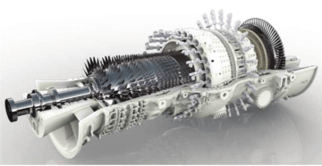
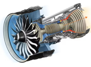
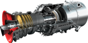
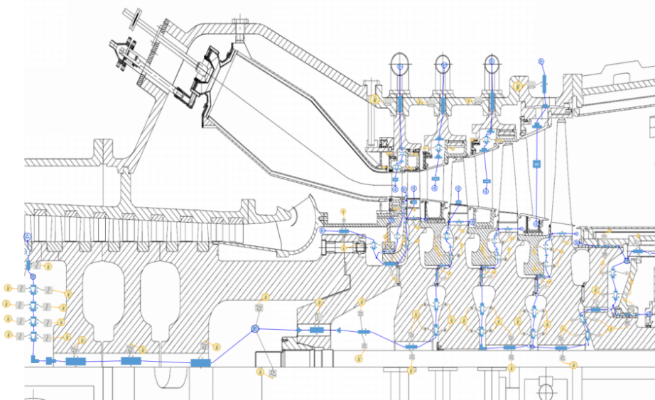
In pumps, compressors, gas turbines, and powertrains with rotating parts, there are typically cavities between the spinning rotor and the fixed stator elements. The flow’s behavior at those cavities can significantly affect a machine’s temperatures, structural loads, vibrations, and overall efficiency. Similar radial cavities, where the flow is restricted between a rotating part and a non-rotating wall, are ubiquitous in the secondary flow channels of gas turbine engines (Figure 1).
![Figure 1 – Example of secondary flows in a gas turbine engine [1]](https://platoaistream.com/wp-content/uploads/2022/12/fluid-swirl-in-radial-channels-of-turbomachines.jpg)
Careful planning of secondary flows can be extremely useful. For example, since secondary flows influence the pressure in cavities, flows can be designed to compensate for axial loads acting on the rotor. Additionally, flow rotation in secondary flow channels critically impacts blade cooling design. For these reasons, a solid understanding of the processes occurring in radial channels is vital for high-quality design and optimization.
A key parameter of the flow in rotor-stator cavities is swirl. Swirl is affected by friction against the walls, and in turn (due to momentum conservation) affects the friction moment acting on the rotor. Thus, a correct calculation of flow swirl is necessary for accurately predicting mechanical losses. Swirl also impacts other important factors, like the heat transfer between the flow and the walls, the static pressure that occurs in cavities, and the flow in subsequent parts of the secondary flow channels.
The literature discussing problems related to swirled flow identifies three main parameters affecting flow structure in rotor-stator cavities: (1) the Reynolds number of the rotor, (2) the geometric ratio (channel width to diameter), and (3) the through-flow coefficient. Depending on the first two parameters, four characteristic types of flow can be distinguished (shown in Figure 2 for a zero through-flow coefficient).

The through-flow coefficient is a dimensionless criterion that represents the ratio of flow rate to the product of the rotor’s size and circumferential speed. In other words, the through-flow coefficient determines the intensity of the flow and its direction (centrifugal or centripetal). In a centripetal flow with a sufficiently large through-flow coefficient, the influence of frictional forces on the walls is less significant than inertial forces, and the flow generally obeys the so-called Free Vortex Law. In contrast, at a low through-flow coefficient, the core of the flow rotates like a solid body (with the same angular velocity along а radius).
However, the topic of swirl in rotor-stator cavities has primarily been studied for simple cases. In certain situations, for example, with strong non-stationarity or with complex geometry, there is good reason to deeply investigate the flow with a CFD simulation.
Engineering practice
Correct calculations of the friction moment acting on the rotor, the heat exchange between the flow and the walls, and the static pressure in the cavities are all crucial for the design and optimization of turbomachines.
With a one-dimensional approach like the one implemented in AxSTREAM NET™, users can simulate the flow in radial channels by creating it on a diagram in the form of a single element. From that, engineers can obtain the integral value of the torque acting on the rotor wall, the flow swirl at the outlet of the element, and the average value of the heat transfer coefficient. Moreover, when it is necessary to consider in detail the distribution of parameters along the radius, a discretization approach of modeling is used. This approach involves dividing the radial channel into the umpteenth number of successive elements. Both approaches are possible in AxSTREAM NET (as shown in Figure 3) due to the implementation of different methodologies into a solver.

Some models implemented in AxSTREAM NET, when applied to a discretized channel, provide the exact distribution of the flow core swirl along the radius. Other models are based on empirical dependencies, and provide a well-verified result for a given range of flow rate or geometric ratios of the channel. The calculated flow swirl is affected by the type of channel (centrifugal or centripetal) and the type of walls adjacent to the channel (rotor or stator walls). In AxSTREAM NET’s library of elements, users can find all corresponding elements to generate just about any channel encountered in practice.
The one-dimensional approach implemented in AxSTREAM NET makes it possible to effectively and accurately solve the problems associated with secondary flows in turbomachinery (Figure 4). The rotor-rotor and rotor-stator cavities are crucial parts in the secondary flow path, and significantly affect the entire system. An accurate estimation of flow parameters in these cavities requires a flexible approach to modeling that is sensitive to geometric data, flow rate values, shaft angular velocity, and other parameters. Usage of implemented correlations in the thermal-fluid network lets us tackle complex tasks like estimating flow swirl.
To learn more about how AxSTREAM NET can help you solve your toughest turbomachinery secondary flow challenges, reach out to us at Sales@Softinway.com
Sources:
- [1] Rolls-Royce plc. The jet engine. 5th ed. reprinted 1996.
- [2] Daily, J.W., Nece, R.E., 1960, Chamber dimension effects on induced flow and frictional resistance of enclosed rotating disks, Journal of Basic Engineering 82, p. 217-232.
- [3] Björn-Christian Will – Theoretical, Numerical and Experimental Investigation of the Flow in Rotor-Stator Cavities with Application to a Centrifugal Pump.
- SEO Powered Content & PR Distribution. Get Amplified Today.
- Platoblockchain. Web3 Metaverse Intelligence. Knowledge Amplified. Access Here.
- Source: https://blog.softinway.com/fluid-swirl-in-radial-channels-of-turbomachines/
- 1
- 1996
- 420
- a
- About
- According
- accurate
- accurately
- Additionally
- affect
- affecting
- against
- All
- and
- Angular
- Application
- applied
- approach
- approaches
- associated
- average
- based
- basic
- between
- BLADE
- body
- calculated
- cases
- certain
- CFD
- challenges
- Chamber
- Channel
- channels
- characteristic
- COM
- complex
- CONSERVATION
- Consider
- contrast
- Core
- Corresponding
- Creating
- crucial
- daily
- data
- Depending
- Design
- designed
- detail
- determines
- different
- Dimension
- direction
- discussing
- Distinguished
- distribution
- ed
- effectively
- effects
- efficiency
- elements
- Engine
- Engineering
- Engineers
- Engines
- Entire
- Ether (ETH)
- example
- exchange
- extremely
- factors
- Figure
- Find
- First
- fixed
- flexible
- flow
- Flows
- Forces
- form
- Free
- friction
- from
- GAS
- generally
- generate
- given
- good
- help
- high-quality
- How
- HTTPS
- identifies
- Impacts
- implementation
- implemented
- important
- in
- In other
- influence
- integral
- investigate
- investigation
- IT
- journal
- Key
- large
- Law
- LEARN
- Lets
- Library
- literature
- loads
- losses
- Low
- Main
- MAKES
- max-width
- mechanical
- methodologies
- models
- moment
- Momentum
- more
- necessary
- net
- network
- number
- ONE
- optimization
- Other
- overall
- parameter
- parameters
- part
- parts
- path
- planning
- plato
- Plato Data Intelligence
- PlatoData
- PLC
- possible
- practice
- predicting
- pressure
- primarily
- problems
- processes
- Product
- provide
- pump
- pumps
- range
- Rate
- ratio
- reach
- reason
- reasons
- related
- represents
- requires
- Resistance
- restricted
- result
- Rolls-Royce
- same
- secondary
- sensitive
- shown
- significant
- significantly
- similar
- Simple
- simulation
- since
- single
- situations
- Size
- solid
- SOLVE
- speed
- strong
- structural
- structure
- studied
- subsequent
- system
- tasks
- The
- theoretical
- three
- to
- topic
- transfer
- TURN
- types
- typically
- ubiquitous
- understanding
- us
- Usage
- users
- value
- Values
- VeloCity
- vital
- W
- will
- words
- Your
- zephyrnet
- zero