From the electricity that charges our phones to the jet engines that propel airplanes across the sky, turbines can be found powering our modern world in various forms and configurations. These mighty machines are the silent heroes of our energy infrastructure, found in everything from locomotives and power plants to industrial machinery and rocket engines. But what distinguishes one turbine from another? How do engineers decide on the design and configuration of these mechanical marvels? This intricate task requires an understanding of turbomachinery design, including axial and radial configurations. So, let’s dive into the differences between an axial and radial configuration.

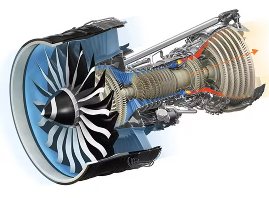
In an axial turbine, the fluid (such as steam, gas, or water) flows along the rotation axis, similar to a windmill where the fluid enters and exits in the same direction. The turbine blades are arranged in stages along the rotor, with each stage converting the fluid’s energy into mechanical energy.
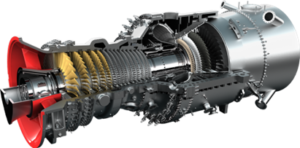
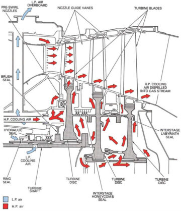
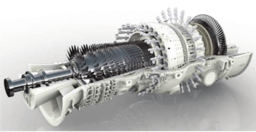
Axial turbines are typically larger and have a higher power output, making them suitable for large-scale, high-speed applications such as power generation in thermal power plants and propulsion in jet engines. Cooling systems are commonly used in axial turbines, especially in high-temperature applications. These cooling systems reduce blade temperatures, prevent overheating, enhance durability, and enable the turbine to operate efficiently at higher temperatures.
However, cooling systems and complex blade designs make the manufacturing and maintenance of axial turbines costly and challenging. Additionally, their size and blade complexity typically results in longer start-up times.

In contrast to axial turbines, radial turbines feature a flow that is perpendicular to the axis of rotation. In a radial-inflow turbine, imagine water spiraling out from a garden sprinkler, but working backwards. This means the ‘water’ enters the turbine in a radial direction, does work on the ‘sprinkler’ to induce rotation, and then exits through the ‘pipe’ beneath it.
Radial turbines, being more compact, are ideal for smaller lower-speed applications. They are mostly found in turbochargers and small power generators. Radial turbines are generally simpler and cheaper to manufacture and maintain, and are particularly beneficial in applications where rapid start-up is important, due to their compact size and robust blades.
Furthermore, a middle ground can be achieved by combining axial and radial turbines in a single system, which can sometimes offer the best of both worlds. Often referred to as a mixed-flow turbine, the fluid first flows radially inward and then turns and exits axially, offering a significant potential advantage.
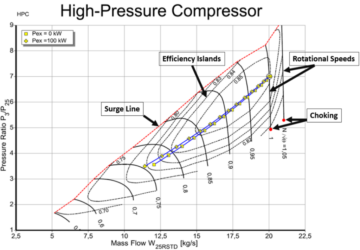
In real-world examples, there could be dozens of different parameters we need to consider in describing the turbine’s performance and determining which configuration is more appropriate. This makes visual comparisons extremely important. The following image (power and total-to-static efficiency versus volume flow rate with different shaft speeds) presents the off-design performance chart for axial and radial turbines under identical conditions. In this specific scenario, the axial turbine attains slightly higher peak efficiency and greater output power for larger capacities. Simultaneously, when the shaft speed deviates from the design point, the efficiency of the axial turbine is less affected. However, we can also observe that when both shaft speed and volume flow rate deviate (as circled in the right graph), the axial turbine demonstrates a narrower range of operation.

In the world of turbomachinery design, the decision of axial or radial hinges on factors like application, operating conditions, size, cost, and start-up time. To solve this challenging task, the ability to simulate different configurations under various operating conditions and iterate these designs in a virtual environment is a game-changer. Interpreting and creating virtual performance charts empowers engineers, fostering confident and precise design decisions. Ultimately, this leads to the creation of efficient and effective turbomachinery designs.
Interested in learning more about different design strategies to determine the optimal turbomachinery configuration? Check out our on-demand webinar discussing this very topic, or register for our September webinar to explore rotor dynamic considerations along with aerodynamic aspects. Links below!
- Choosing the Optimal Turbomachinery Configuration Leveraging Generative Design: View Recording
- Selecting the Ideal Turbomachinery Configuration Considering Rotor Dynamic Constraints: Register
Reference:
[1] Kurzke, J. (2018). Propulsion and Power: An Exploration of Gas Turbine Performance Modeling. Springer. [2] https://learn.softinway.com/Webinar/Watch/153 [3] https://www.machinedesign.com/motors-drives/article/21832035/whats-the-difference-between-turbine-engines- SEO Powered Content & PR Distribution. Get Amplified Today.
- PlatoData.Network Vertical Generative Ai. Empower Yourself. Access Here.
- PlatoAiStream. Web3 Intelligence. Knowledge Amplified. Access Here.
- PlatoESG. Automotive / EVs, Carbon, CleanTech, Energy, Environment, Solar, Waste Management. Access Here.
- PlatoHealth. Biotech and Clinical Trials Intelligence. Access Here.
- ChartPrime. Elevate your Trading Game with ChartPrime. Access Here.
- BlockOffsets. Modernizing Environmental Offset Ownership. Access Here.
- Source: https://blog.softinway.com/turbomachinery-design-strategies-tips-how-to-choose-between-an-axial-or-radial-configuration/
- :is
- :where
- 1
- 2018
- 3d
- a
- ability
- About
- achieved
- across
- Additionally
- ADvantage
- Airplanes
- along
- also
- an
- and
- Another
- Application
- applications
- appropriate
- ARE
- arranged
- AS
- aspects
- At
- Axis
- BE
- being
- beneficial
- BEST
- between
- BLADE
- both
- but
- by
- CAN
- capacities
- challenging
- charges
- Chart
- Charts
- cheaper
- check
- choosing
- combining
- commonly
- comparison
- complex
- complexity
- conditions
- confident
- Configuration
- Consider
- considerations
- considering
- constraints
- contrast
- converting
- Cost
- costly
- could
- Creating
- creation
- decide
- decision
- decisions
- demonstrates
- Design
- designs
- Determine
- determining
- differences
- different
- direction
- discussing
- do
- does
- dozens
- due
- durability
- dynamic
- each
- Effective
- efficiency
- efficient
- efficiently
- electricity
- empowers
- enable
- energy
- Engine
- Engineers
- Engines
- enhance
- Enters
- Environment
- especially
- everything
- example
- examples
- exits
- exploration
- explore
- extremely
- factors
- Feature
- First
- flow
- Flows
- fluid
- following
- For
- forms
- fostering
- found
- from
- game-changer
- Garden
- GAS
- generally
- generation
- generative
- generators
- graph
- greater
- Ground
- Have
- Heroes
- higher
- How
- However
- HTTPS
- ideal
- identical
- image
- imagine
- important
- in
- Including
- industrial
- Infrastructure
- into
- IT
- large-scale
- larger
- Leads
- learning
- left
- less
- leveraging
- like
- links
- longer
- machinery
- Machines
- made
- maintain
- maintenance
- make
- MAKES
- Making
- manufacturing
- max-width
- means
- mechanical
- Middle
- mighty
- modeling
- Modern
- more
- mostly
- Need
- observe
- of
- offer
- offering
- often
- on
- On-Demand
- ONE
- operate
- operating
- operation
- optimal
- or
- our
- out
- output
- parameters
- particularly
- Peak
- performance
- phones
- plants
- plato
- Plato Data Intelligence
- PlatoData
- Point
- potential
- power
- power plants
- Powering
- precise
- presents
- prevent
- Propel
- propulsion
- range
- rapid
- Rate
- real world
- reduce
- referred
- register
- requires
- Results
- right
- robust
- rocket
- same
- scenario
- September
- significant
- similar
- simultaneously
- single
- Size
- sky
- small
- smaller
- So
- SOLVE
- sometimes
- specific
- speed
- speeds
- Stage
- stages
- Start-up
- Steam
- strategies
- such
- suitable
- system
- Systems
- Task
- that
- The
- the world
- their
- Them
- then
- There.
- thermal
- These
- they
- this
- Through
- time
- times
- to
- topic
- turbine
- turns
- typically
- Ultimately
- under
- understanding
- used
- various
- Versus
- very
- Virtual
- volume
- Water
- we
- webinar
- What
- when
- which
- with
- Work
- working
- world
- world’s
- zephyrnet