Fabrication of phototransistor arrays for the artificial retina
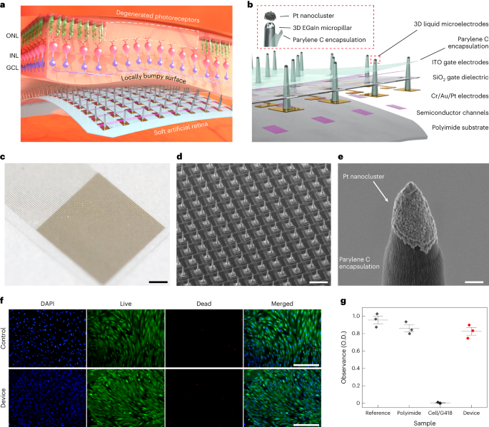
The device consists of Si channels (340 nm), Cr (5 nm)/Au (100 nm)/Pt (30 nm) source (S)/drain (D)/interconnect electrodes, SiO2 dielectric layer (500 nm) and indium tin oxide gate (G) electrode (150 nm). The Si channel, which is a representative photoabsorbing semiconductor, was chosen as a proof of concept, but it can be easily replaced by other alternatives with higher sensitivity and flexibility (that is, two-dimensional materials) to further enhance the optoelectronic performance of artificial retinas. For the fabrication of these phototransistor arrays, first, an array of single-crystalline Si, which serves as the channel of the transistor, was photolithographically patterned using a positive photoresist (S1818, MicroChem) on a silicon-on-insulator wafer (340 nm boron-doped p-type Si with a resistivity of 8.5 Ω cm on 400 nm buried oxide; Soitec). This transistor array was fabricated on a thin and transparent polyimide film (thickness, 8 μm). The Si channels were etched with an RIE system with sulfur hexafluoride (SF6) plasma (SF6 25 s.c.c.m./Ar 55 s.c.c.m.; 300 W/40 s), completing the channel isolation process. Any subsequently remaining photoresist residue was removed using a piranha solution (10 min). To separate the Si channel from the silicon-on-insulator wafer, the buried oxide layer was etched in a 50% hydrogen fluoride solution for 18 min. Second, the pattern of Si channels was transferred from a silicon-on-insulator wafer onto the flexible and transparent polyimide film (8 μm) using a polydimethylsiloxane stamp (SYLGARD 184, 10:1 weight ratio of base and curing agent). Cr 5 nm/Au 100 nm were deposited using an electron-beam evaporator and were photolithographically patterned to form a source (S) electrode, a drain (D) electrode and interconnects41,42,43. Then, a sacrificial layer (LOR 3A photoresist, Kayaku) was spun on the substrate and photolithographically patterned, and this was followed by the deposition of 30-nm-thick Pt on the opened area with an electron-beam evaporator. This metal layer was deposited to prevent the penetration of gallium atoms to the Au drain electrodes. Subsequently, silicon dioxide (SiO2) was deposited with a thickness of 500 nm at 150 °C using plasma-enhanced chemical vapour deposition, and it was photolithographically patterned as a dielectric layer. Then, for the patterning of the gate (G) electrode, a sacrificial layer (LOR 3A photoresist, Kayaku) was spun on the substrate and photolithographically patterned. Indium tin oxide was deposited as a gate electrode with a thickness of 150 nm at room temperature by radio-frequency magnetron sputtering, and it was immersed in mr-Rem 700 (lift-off solution, micro resist technology) at 60 °C for 30 min to melt the sacrificial layer. As a biocompatible encapsulation layer, a 1-μm-thick layer of parylene C was deposited and photolithographically patterned by dry etching with RIE (O2 40 s.c.c.m., 100 W/240 s) to open the area for the direct printing of 3D LM microelectrodes.
Fabrication of 3D LM microelectrodes
The key steps in the fabrication of the 3D LM microelectrodes are as follows:
(1) Direct printing of 3D pristine EGaIn electrodes: the direct printing system consists of a capillary nozzle connected to an ink reservoir; a pneumatic pressure controller and a six-axis stage with automatic movements in the x, y and z axes; two tilting axes in the x and y axes; and rotation in the x–y plane. First, a pipette puller (P-1000, Sutter Instrument) was used to make a glass capillary (Sutter Instrument) as a nozzle with inner diameters of 5 to 50 μm. Then, a nozzle was mounted onto a syringe-type reservoir, and a substrate was placed on the six-axis stage. All of the LM printing steps were recorded by the microscope camera (QImaging MicroPublisher 5.0 with real-time viewing, Teledyne Photometrics) to control the nozzle from the substrate using the six-axis stage (H-820 6-Axis Hexapod, Physik Instrumente) during the printing process. The distance between the tip of the nozzle and the substrate was controlled to be in the range of 2–16 μm according to the diameter of the nozzle, and the pneumatic pressure (∼50 psi) was applied to deliver the EGaIn ink (75.5% gallium and 24.5% indium alloy by weight; Changsha Santech Materials) from a reservoir onto the substrate through the nozzle. After we controlled the z axis of the six-axis stage to make contact between EGaIn and the opened area of the drain electrode, the ink was directly printed in a circular shape on the top surface of the drain to exhibit a thicker base of the 3D micropillar for its structural stability. By adjusting the printing motion along the z axis at a velocity in the range of 1 to 500 μm s–1, the 3D pillar of EGaIn with a uniform diameter (except the circular base part) can be printed (Supplementary Video 1). On exposure to air, EGaIn instantaneously forms a thin solid layer (∼1 nm) of gallium oxide on its surface under atmospheric oxygen levels to maintain its vertical 3D structure of EGaIn. This oxide skin is thin enough to avoid substantially damaging the cellular interfaces, and it is solid enough to maintain its 3D shape against gravity and surface tension.
(2) Selective opening of 3D electrode tips: after the printing of the 3D pristine EGaIn electrodes, additional parylene C (thickness, 1 μm) was deposited on the entire device, including the 3D electrodes for the passivation of their sidewalls. Only their tips were selectively opened using anisotropic O2 RIE (100 W/240 s), as the additional parylene C encapsulating layer served as a protective layer of the first parylene C encapsulation layer as well as the encapsulation layer of the sidewalls of the 3D micropillars.
(3) Deposition of Pt nanoclusters: to prepare 50 ml of an electroplating solution, we mixed 50 ml of deionized water, 10 mg of lead acetate trihydrate (Sigma-Aldrich) and 0.5 g of platinum tetrachloride (Sigma-Aldrich) at room temperature. This electroplating solution was stirred for 20 min by ultrasonic vibration. The electroplating was performed by ion transfer between the cathode and anode in the Pt electroplating solution. After mounting the device to a multichannel recording interface (MZ-60, Tucker-Davis Technologies), a cathode (the 3D pristine EGaIn microelectrode that is to be electroplated) and an anode (Ti/Pt electrode) were immersed in this electroplating solution, and each electrode was connected to a source meter (Keithley 2400, Tektronix). An electrical current of 0.1 mA was applied for 60 s to generate the electroplating reaction (Supplementary Fig. 25). Due to potential variations in currents under light exposure, we performed the electroplating of Pt nanoclusters in the dark state.
(3) Rinsing process of the artificial retina: before the implantation of the device, we rinsed the artificial retina by gently immersing the device in 70% ethanol solution (15 min) and deionized water (15 min) followed by ultraviolet exposure (30 min).
Ex vivo animal experiments
Ex vivo experiments were conducted based on the guidelines and were approved by the Institute of Animal Care and Use Committee of Yonsei University (IACUC-A-201911-985-01, IACUC-202011-1164-05, Yonsei IACUC). The recording involved the retinas of five mice for both WT and rd1 type, and for the recording of retinal responses (that is, visually or electrically evoked retinal spike potentials and firing rate of the spikes); each recording electrode was positioned adjacent to each stimulation electrode (pitch between the stimulating and recording electrodes, 40 μm). The retinas of both WT mice (C57BL/6J, Japan SLC) and rd1 mice (C3H/HeJ, Japan SLC) were explanted, and small pieces (∼4 × 4 mm) were isolated and transferred to the artificial retina with the phosphate-buffered saline medium by RGCs facing the device, and a heating pad was used to maintain the temperature of the retinas at 37 °C. The animal was immediately sacrificed after extraction. The isolated retinas from WT and rd1 mice were directly placed on our device (consisting of 36 stimulating and recording electrode pairs), and our 3D electrodes were directed towards the RGC side of the retina in phosphate-buffered saline media. Immediately before implanting this device into the retina, the device sample was instantly frozen to turn the liquid-phase EGaIn into a solid by leaving it in cold storage (below the melting point of EGaIn, ∼15.7 °C). Then, the protrudent pillar shape of the 3D electrodes returned to a liquid phase and did not collapse even after being implanted into the retina.
Since mice are dichromatic mammals having only two cone types (blue and green light sensitive)42,43, the blue light (wavelength, 470 nm) was used for exposure in this experiment. For electrical stimulation, the transistor of our device was operated with a specific condition (VG, d.c. bias of 5 V; VD: pulsed bias of 1 V with a duration of 1 ms and frequency of 10 Hz) and the recordings were performed with the adjacent recording electrodes. Electrophysiological recordings of the retina were conducted by multielectrode array recording and multichannel stimulation (PZ5 and Subject Interface, Tucker-Davis Technologies) and a data processor with a real-time controller (RZ2 BioAmp Processor, Tucker-Davis Technologies). We recorded the VEP and EEP signals at a 25 kHz sampling rate using a 300 Hz low-pass filter and 3,000 Hz high-pass filter. The experimental data were processed further by applying a band-pass filter with MATLAB R2021a (MathWorks). No data points were excluded from the analyses.
In vivo implantation
The rd1 mice (n = 3) were anaesthetized with an intraperitoneal injection of a mixture of tiletamine and zolazepam (1:1, 15 mg kg–1 body weight) and xylazine hydrochloride (10 mg kg–1 body weight). The pupils of the mice were dilated with eye drops that contained 0.5% phenylephrine and 0.5% tropicamide. The body temperatures of the mice were maintained at 37 °C with a heating pad.
For the surgical procedures, the mouse was placed in a head holder to maintain the head in a fixed position and to allow access to the eye. The head holder was placed under an optical microscope with an illuminator. A clear 2.2 mm corneal knife (KAI MEDICAL; CCR-22AGF) was used to make a 1.5 mm incision in the area of the pars plana. Immediately before implanting this device into the retina, the device sample was instantly frozen to turn the liquid-phase EGaIn into a solid by leaving it in cold storage (below the melting point of EGaIn, that is, ∼15.7 °C). Then, it was implanted into the vitreous cavity (that is, attached to the retinal surfaces) via the incision that was made earlier. For preventing cataracts during a continuous functional analysis, a 10 g drop of hypromellose (Hycell oph soln) was applied to the surface of the cornea. During this in vivo experiment, a hydrogel-based artificial vitreous body was initially filled in the vitreous cavity of the mouse eye to prevent undesired side effects, such as hypotony (low intraocular pressure). After the experiment, the mice were immediately euthanized by carbon dioxide inhalation in a carbon dioxide chamber. No statistical methods were used to predetermine the sample sizes, but our sample sizes are similar to those reported in previous publications9,11.
In vivo animal experiments
In vivo experiments were conducted based on the guidelines of the Institute of Animal Care and Use Committee of Yonsei University (IACUC-A-202205-1478-01, Yonsei IACUC). Considering the size of the eyeball of a mouse (diameter, ∼3 mm), we fabricated an artificial retina integrated with 6 × 6 arrays of phototransistors (pixel pitch, 200 μm; device width, 2 mm) with 3D LM microelectrodes (height, 60 μm; diameter, 20 μm). This artificial retina was implanted into the innermost retinal surface of the rd1 mouse epiretinal, with external device interconnections. All the devices and animals tested were randomly selected. The recording lines were connected to the glass pad with interconnect electrodes and then patterned with photolithography and wet etching after the deposition of Cr/Au (10/100 nm) by an electron-beam evaporator. The interconnect pad was inserted into the multielectrode array recorder with a multichannel stimulator (PZ5 and Subject Interface, Tucker-Davis Technologies) and a data processor with a real-time controller (RZ2 BioAmp Processor, Tucker-Davis Technologies). The multichannel experimental data of the spike signal and firing rate were obtained and exported by analysis software (Synapse Suite version 94, Tucker-Davis Technologies). Then, the data were processed and mapped with MATLAB R2021a (MathWorks) and Origin 2022b software. Full-field light illumination (470 nm, TouchBright T1 with BN470 band-pass filter, Live Cell Instrument) or a laser (wavelength, 415 nm) through an ellipsoidal pattern of a shadow mask was applied to the fundus of the mouse’s eye for light exposure (duration, 5 s). No data points were excluded from the analyses. Also, data met the assumptions of the statistical tests used.
Statistical analysis
All data were presented as mean ± standard deviation (s.d.). Statistical calculations of P value were performed using an open-source code of MATLAB R2021a. Significance was calculated using an unpaired one-tailed t-test.
Reporting summary
Further information on research design is available in the Nature Portfolio Reporting Summary linked to this article.
- SEO Powered Content & PR Distribution. Get Amplified Today.
- PlatoData.Network Vertical Generative Ai. Empower Yourself. Access Here.
- PlatoAiStream. Web3 Intelligence. Knowledge Amplified. Access Here.
- PlatoESG. Carbon, CleanTech, Energy, Environment, Solar, Waste Management. Access Here.
- PlatoHealth. Biotech and Clinical Trials Intelligence. Access Here.
- Source: https://www.nature.com/articles/s41565-023-01587-w
- :is
- :not
- 000
- 1
- 10
- 100
- 11
- 15%
- 150
- 17
- 20
- 200
- 2018
- 2020
- 2022
- 24
- 25
- 30
- 300
- 36
- 3d
- 40
- 400
- 43
- 50
- 500
- 60
- 7
- 700
- 75
- 8
- 9
- a
- access
- According
- Additional
- adjacent
- adjusting
- After
- against
- Agent
- AIR
- AL
- All
- allow
- Alloy
- along
- also
- alternatives
- an
- analyses
- analysis
- Anchor
- and
- animal
- animals
- any
- applied
- Applying
- approved
- ARE
- AREA
- Array
- article
- artificial
- AS
- assumptions
- At
- atmospheric
- Automatic
- available
- avoid
- AXES
- Axis
- base
- based
- BE
- before
- being
- below
- between
- bias
- blind
- Blue
- body
- both
- but
- by
- calculated
- camera
- CAN
- carbon
- carbon dioxide
- care
- cell
- cellular
- Chamber
- Channel
- channels
- chemical
- chosen
- clear
- click
- code
- cold
- Cold Storage
- Collapse
- color
- committee
- completing
- concept
- condition
- conducted
- connected
- considering
- Consisting
- consists
- contact
- contained
- continuous
- control
- controlled
- controller
- curing
- Current
- cytotoxicity
- D.C.
- damaging
- Dark
- data
- data points
- deliver
- deposited
- Design
- deviation
- device
- Devices
- DID
- direct
- directed
- directly
- distance
- drain
- Drop
- Drops
- dry
- due
- duration
- during
- E&T
- each
- Earlier
- easily
- effects
- emergence
- engineered
- enhance
- enough
- Entire
- Ether (ETH)
- evaluation
- Even
- Except
- excluded
- exhibit
- experiment
- experimental
- experiments
- Exposure
- express
- external
- extraction
- eye
- facing
- Fig
- filled
- Film
- filter
- firing
- First
- five
- fixed
- Flexibility
- flexible
- followed
- follows
- For
- form
- forms
- Frequency
- from
- frozen
- functional
- further
- gate
- generate
- glass
- gravity
- Green
- green light
- guidelines
- having
- head
- height
- higher
- holder
- HTTPS
- human
- hydrogen
- image
- immediately
- immersed
- in
- Including
- information
- initially
- inner
- instantaneously
- instantly
- Institute
- instrument
- integrated
- Interface
- interfaces
- International
- into
- involved
- ISO
- isolated
- isolation
- IT
- ITS
- Japan
- Key
- laser
- layer
- lead
- leaving
- levels
- light
- lines
- LINK
- linked
- Liquid
- live
- Low
- made
- maintain
- make
- mask
- material
- materials
- mean
- Media
- medical
- medical devices
- medium
- met
- metal
- methods
- methods Were
- mice
- micro
- Microscope
- min
- mixed
- mixture
- ML
- model
- motion
- mouse
- movements
- MS
- multichannel
- nanotechnology
- Natural
- Nature
- no
- novel
- obtained
- of
- on
- ONE
- only
- open
- open source
- open-source code
- opened
- opening
- operated
- or
- organization
- Origin
- Other
- our
- Oxygen
- pad
- pairs
- part
- Pattern
- penetration
- performance
- performed
- phase
- pieces
- Pillar
- Pitch
- Pixel
- placed
- plane
- Plasma
- platinum
- plato
- Plato Data Intelligence
- PlatoData
- Point
- points
- polymer
- portfolio
- position
- positioned
- positive
- potential
- potentials
- Prepare
- presented
- pressure
- prevent
- preventing
- previous
- printing
- procedures
- process
- processed
- Processor
- proof
- proof of concept
- Protective
- range
- RAT
- Rate
- ratio
- reaction
- real-time
- recorded
- recording
- reference
- remaining
- Removed
- replaced
- Reported
- Reporting
- representative
- rescue
- research
- responses
- restoration
- restore
- Retina
- Room
- s
- Science
- Second
- selected
- selective
- semiconductor
- sensitive
- Sensitivity
- separate
- served
- serves
- Shadow
- Shape
- side
- Signal
- signals
- significance
- Silicon
- similar
- Size
- sizes
- Skin
- small
- Software
- solid
- solution
- Source
- specific
- spike
- spikes
- spun
- Stability
- Stage
- stamp
- standard
- standardization
- State
- statistical
- statistics
- Steps
- storage
- structural
- structure
- subject
- Subsequently
- substantially
- such
- suite
- Surface
- surgical
- Synapse
- system
- T1
- tang
- Technologies
- Technology
- tested
- tests
- that
- The
- The Area
- their
- then
- These
- this
- those
- three-dimensional
- Through
- tip
- tips
- to
- top
- towards
- transfer
- transferred
- transparent
- TURN
- two
- type
- types
- Ultrasonic
- under
- university
- use
- used
- using
- value
- variations
- VeloCity
- version
- vertical
- via
- Video
- viewing
- vision
- visually
- vivo
- was
- Water
- we
- weight
- WELL
- were
- which
- Williams
- with
- zephyrnet