For those looking to add wireless connectivity to embedded projects or to build IoT devices, there is perhaps no more popular module than the ESP32. A dual-core option exists for processor intensive applications, the built-in WiFi and Bluetooth simplify designs, and it has plenty of I/O, memory, and interoperability for most applications. With so much built into the chip itself, [atomic14] wondered how much support circuitry it really needed and set about building the most minimalist ESP32 development board possible.
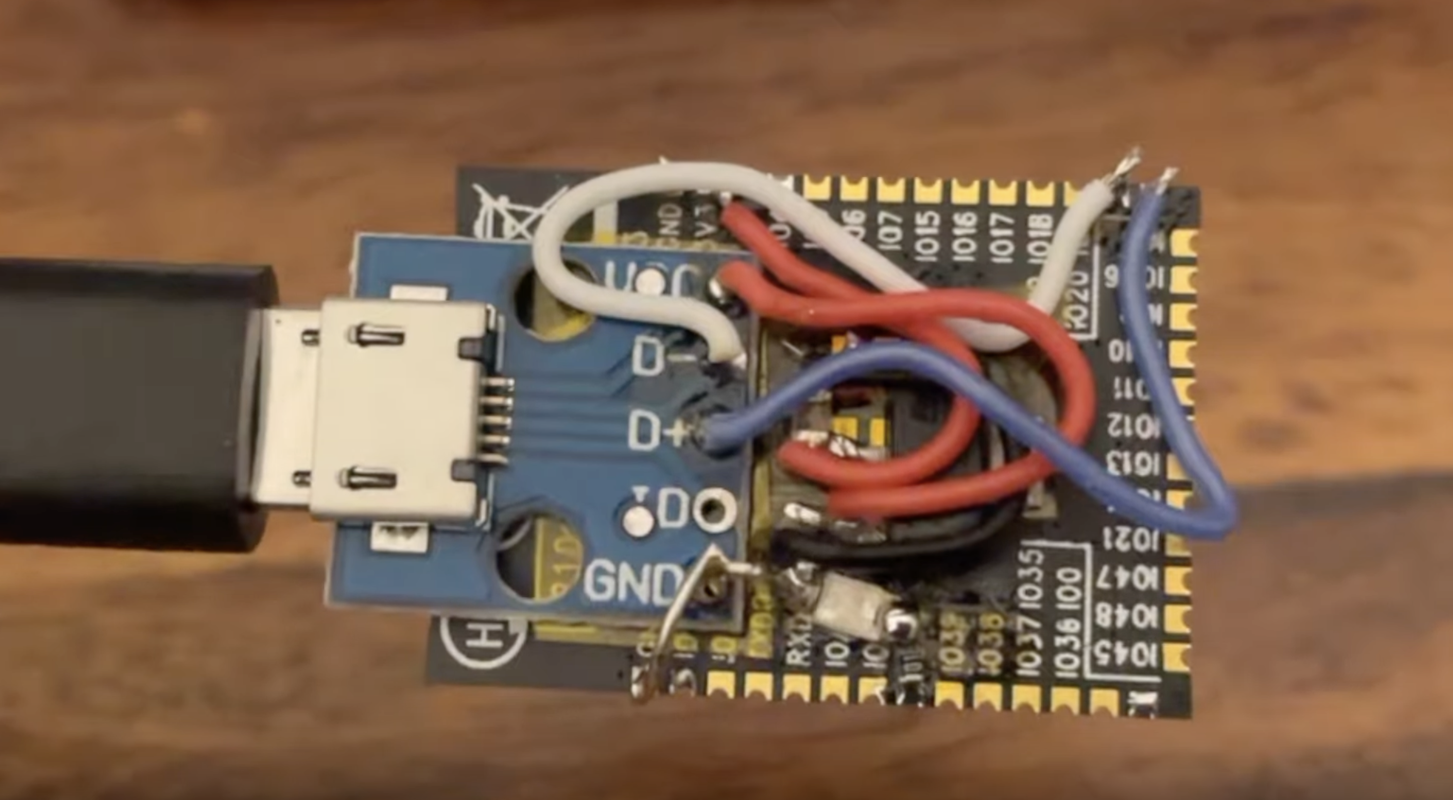
Starting with the recommended schematic for the ESP32, the most obvious things to remove are a number of the interfacing components like the USB to UART chip and the JTAG interface. The ESP32 has USB capabilities built in, so the data lines from a USB port can be directly soldered to the chip instead of using a go-between. A 3.3V regulator eliminates the need for many of the decoupling capacitors, and the external oscillator support circuitry can also be eliminated when using the internal oscillator. The only thing [atomic14] adds that isn’t strictly necessary is an LED connected to one of the GPIO pins, but he figures the bare minimum required to show the dev board can receive and run programs is blinking an LED.
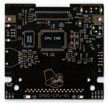
Building the circuit on a breadboard shows that this minimalist design works, but instead of building a tiny PCB to solder the ESP32 module to he attempted to build a sort of dead-bug support circuit on the back of the ESP32. This didn’t work particularly well so a tiny dev board was eventually created to host this small number of components. But with that, the ESP32 is up and running. These modules are small and compact enough that it’s actually possible to build an entire dev board setup inside a USB module for a Framework laptop, too.
- SEO Powered Content & PR Distribution. Get Amplified Today.
- PlatoData.Network Vertical Generative Ai. Empower Yourself. Access Here.
- PlatoAiStream. Web3 Intelligence. Knowledge Amplified. Access Here.
- PlatoESG. Automotive / EVs, Carbon, CleanTech, Energy, Environment, Solar, Waste Management. Access Here.
- BlockOffsets. Modernizing Environmental Offset Ownership. Access Here.
- Source: https://hackaday.com/2023/07/28/the-esp32-doesnt-need-much/
- :has
- :is
- $UP
- a
- About
- actually
- add
- Adds
- also
- an
- and
- applications
- ARE
- attempted
- back
- BE
- bluetooth
- board
- build
- Building
- built
- built-in
- but
- CAN
- capabilities
- chip
- components
- connected
- Connectivity
- content
- created
- data
- Design
- designs
- Dev
- Development
- Devices
- directly
- Doesn’t
- eliminated
- eliminates
- embedded
- enough
- Entire
- ESP32
- eventually
- exists
- external
- Figures
- For
- Framework
- from
- he
- host
- How
- HTTPS
- in
- inside
- instead
- Interface
- internal
- Interoperability
- into
- iot
- iot devices
- IT
- itself
- Led
- like
- lines
- looking
- many
- Memory
- minimum
- module
- Modules
- more
- most
- much
- necessary
- Need
- needed
- no
- number
- obvious
- of
- on
- ONE
- only
- Option
- or
- particularly
- perhaps
- pins
- plato
- Plato Data Intelligence
- PlatoData
- Plenty
- Popular
- possible
- Processor
- Programs
- projects
- really
- receive
- recommended
- regulator
- remove
- required
- Run
- running
- set
- setup
- show
- Shows
- simplify
- small
- So
- support
- than
- that
- The
- There.
- These
- thing
- things
- this
- those
- to
- too
- true
- usb
- using
- was
- WELL
- when
- wifi
- wireless
- with
- Work
- works
- youtube
- zephyrnet