We often use linear regulators in our designs. They are cheap and simple – you put the regulator chip itself on the board, add two capacitors, and get a voltage. Linear regulators are imperfect, of course – they can’t help but waste the voltage difference as heat, for a start, which straight up excludes them for high-current purposes, or significant voltage difference conversions, unless you have a hefty heatsink handy. They also can’t boost voltage, which means you can only go from high to low – a bit of a disappointment.
Of course, we haven’t been just throwing our hands up in the air if a linear regulator doesn’t fit our purpose. Switching regulators have none of these disadvantages, which is why your mobile phone alone has a few dozen of these. They are way more efficient and hi-tec, able to convert one voltage into another while losing hardly any power into heat. All that you need to do is switch an inductor at a somewhat high frequency!
 However, for some, switching regulators might look a bit intimidating. They tend to have higher standards for board layout compared to linear regulators, and, they do need an inductor – sometimes, a few more components too. Inductors alone are somewhat intimidating components, with a fair few more parameters than we’d expect, and you might get confused when looking into adding a switching regulator to your circuit.
No more! In this article, I shall give you the switching regulator basics, remove any fog of war that might be clouding your vision, and show you just how easily you can get a good few amps at your favourite voltage whenever you need it.
Finding Your Faves
There’s myriads of switching regulators you can use for many different purposes! For instance, buck regulators can only decrease voltage, boost regulators can only increase it, while buck-boost can do both, allowing you to get, say, 12V from a LiIon pack that varies from 10V to 14.4V. There’s two ways you can find yourself some switching regulator friends – either getting part numbers from somebody else’s circuits, or by going through Digikey/Mouser/etc and seeing their offerings.
There are switching regulators for most purposes you could think of. Want to convert 12V into a few amps of 5V or 3.3V? You have a ton options here! Want to make 5V or 3.3V out of LiIon voltage? There’s a good number of regulators for this exact purpose! An extremely low-power regulator that produces 3.3V for your ESP8266 from two AA batteries? You got it! And, the simplest option possible is borrowing a circuit from an existing reasonably-open or just publicly visible design.

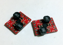
For instance, there’s a ton of different “DC-DC” boards you can quickly find online – on Aliexpress alone, there’s dozens of popular designs, and a good amount of more obscure ones too. Simply enter “step-down DC-DC 5V”, any configuration/voltage you want, find a few listings which are actually accurate, and see which chip they’re using. Can you find the datasheet? Can you buy it easily? Some listings lie about current values, so, can the chip actually produce what you need? If so, you are set!
Of course, for many purposes, you can reuse those modules and not worry about even looking for your own designs. However, most often, making your own switching regulator circuit will pay off – both in price, but also in your circuit’s stability! For instance, an open secret is that these modules tend to have badly suited inductors, either cheapest parts possible or just miscalculated values. So often, you only have to replace the inductor to see the output current skyrocket, and see the heat output decrease overall, too!
Often, the switching regulator ICs used on these modules, are also the cheapest chips possible, and there’s better ICs available for hardly more money. So, go visit the switching regulator parts picker of your favourite parts website – Digikey/LCSC/Mouser or whatever else. Put in your desired input and output voltage ranges, maximum current with some leeway, check “In stock”, sort by price, and see just how far you can get under $1!
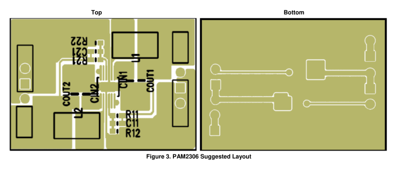
My personal faves recently are a good few. PAM2306 is a dual-rail 3.3V/1A buck regulator able to do 100% duty cycle, which helps a ton when powering stuff from a LiIon or LiFePO4 battery. AP63200 can do 5V or 3.3V at 2A from as high as 30V, which is rad for my USB-PD shenanigans! And, on the Eastern front, SY8089 is a good pick for general low-voltage rails. Got some regulators you’d recommend to others? Share them with us in the comment section!
Found a chip you like? Cheers! The overwhelming majority of them need an inductor. Let’s waste no time and learn about those.
Meet The Inductor
Inductors are coils of wire made in a certain way, able to store a good amount of electromagnetic energy under the right circumstances. They also resist changes in current by producing an opposite voltage. Someone more inductor-savvy than me could tell you a ton about how inductors are seriously cool, and they absolutely are very cool! And, for switching regulator use, you don’t need to know a lot about inductors to use them. What you do need to know is that a switching regulator chip makes use of these characteristics to convert one voltage into another, and there’s only three parameters you really need to keep track of.
First one is inductance, usually, in uH (microHenry) range. Your switching regulator’s datasheet will either straight up tell you which inductance value is a good fit, maybe in the example schematic or in the “recommended parameters” section, or, it will give you a formula to calculate the inductance you need. If it doesn’t give you either of these two, look into values that other people use with this chip, or pick a different chip – more often than not, there’s other switching regulator chips you can use just as easily and that actually have good datasheets.

Another value is DC current. Again, a lot of datasheets will straight up hold your hand while walking you through inductor selection, and the PAM2306 datasheet I show above, tells you that DC current is your maximum current plus ripple current, and you can assume ripple current to be 40% of maximum current you want. If you want to know for sure, the datasheet gives a formula to calculate a more precise value, but generally, the datasheets I’ve checked, do tell you to add 40-50%. So, if you pick inductor DC current to be 1.5 times larger than the max current you want, you likely won’t go wrong.
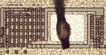
You might also see a specific parameter, DC resistance. The lower, the better, of course – less current wasted as heat. It’s not just waste, either – the kind of inductors used in switching regulator applications have their characteristics rapidly worsen when they heat up. Also, some inductors aren’t at their best when being used for switching regulator purposes, even if they look the part. Here’s an example of such an inductor. This is a power rail filtering inductor, and if that’s what you stumbled upon, there’s likely a power inductor (the kind you use for switching purposes) available with better specs that’s a much better fit for your application – not that it’s 100% unusable, but you will benefit from looking further.
Let’s sum up just how simple it is to find an inductor. Three parameters – inductance, DC current, and DC resistance. Inductance is in the datasheet, DC current is your desired max current times 1.5 give or take, and third is as low as you can go for your money. Plus, check that the inductor is suited for switching regulator applications. Looking to learn more? Here’s some appnotes – here’s a Wurth appnote on inductor intricacies, and a TI appnote on switching regulator basics.
Go to your favourite component picker website – Digikey, Mouser, LCSC or anything else, – put the inductance and DC current parameters into the inductor part picker, find the best DC resistance for your money, and you’re set. Hell, you can even find inductors on Aliexpress! They don’t tend to list DC current/resistance parameters, and datasheets are few and far between, but if you need something simple and cheap, it’s on the table.
 Found an inductor? Get the datasheet, see if KiCad already has a fitting footprint, if not, just take an existing footprint and adjust it, and that’s it. We got the regulator chip, we got the inductor picked, now it’s time to design a board!
In Case You Get Lost
If your regulator’s datasheet is good, you are already set. The best datasheets provide an example layout, show you which resistors to use, mention any extra components, capacitor requirements, and teach you everything else you could want to know.
Not all of the datasheets contain everything you’d want to know, however. It’s a bummer, but, it doesn’t mean you can’t get it done! There are only a few aspects to mind – board layout, feedback resistors, and any extra components you might need. Next time, let’s go through these, and I’ll show you some switching regulator tips&tricks too!
- SEO Powered Content & PR Distribution. Get Amplified Today.
- PlatoData.Network Vertical Generative Ai. Empower Yourself. Access Here.
- PlatoAiStream. Web3 Intelligence. Knowledge Amplified. Access Here.
- PlatoESG. Carbon, CleanTech, Energy, Environment, Solar, Waste Management. Access Here.
- PlatoHealth. Biotech and Clinical Trials Intelligence. Access Here.
- Source: https://hackaday.com/2024/01/22/switching-regulators-for-dummies/
- :has
- :is
- :not
- $UP
- 1
- 14
- 180
- 1800
- 2000
- 250
- 361
- 438
- a
- Able
- About
- above
- absolutely
- accurate
- actually
- add
- adding
- adjust
- again
- AIR
- All
- Allowing
- alone
- already
- also
- amount
- AMPs
- an
- and
- Another
- any
- anything
- Application
- applications
- ARE
- article
- AS
- aspects
- assume
- At
- available
- badly
- Basics
- batteries
- battery
- BE
- been
- being
- benefit
- BEST
- Better
- between
- Bit
- board
- boost
- Borrowing
- both
- but
- buy
- by
- calculate
- CAN
- Can Get
- case
- certain
- Changes
- characteristics
- cheap
- cheapest
- check
- checked
- chip
- Chips
- circumstances
- comment
- compared
- component
- components
- confused
- contain
- conversions
- convert
- Cool
- could
- course
- Current
- cycle
- dc
- decrease
- Design
- designs
- desired
- difference
- different
- disappointment
- do
- Doesn’t
- Dont
- dozen
- dozens
- easily
- eastern
- efficient
- either
- else
- Else’s
- energy
- Enter
- Even
- everything
- example
- existing
- expect
- extra
- extremely
- fair
- far
- feedback
- few
- filtering
- Find
- fit
- fitting
- Fog
- Footprint
- For
- formula
- friends
- from
- front
- further
- General
- generally
- get
- getting
- Give
- gives
- Go
- going
- good
- got
- hand
- Hands
- handy
- Have
- help
- helps
- High
- higher
- hold
- How
- However
- HTTPS
- i
- I’LL
- ICS
- if
- in
- Increase
- input
- instance
- intimidating
- into
- intricacies
- IT
- itself
- just
- Keep
- Kind
- Know
- larger
- Layout
- LEARN
- less
- lie
- like
- likely
- List
- Listings
- Look
- looking
- losing
- Lot
- Low
- lower
- made
- Majority
- make
- MAKES
- Making
- many
- max
- max-width
- maximum
- maybe
- me
- mean
- means
- mention
- might
- mind
- Mobile
- mobile phone
- Modules
- money
- more
- more efficient
- most
- much
- my
- Need
- next
- no
- None
- now
- number
- numbers
- of
- off
- Offerings
- often
- on
- ONE
- ones
- online
- only
- open
- opposite
- Option
- Options
- or
- Other
- Others
- our
- out
- output
- overall
- overwhelming
- own
- Pack
- parameter
- parameters
- part
- parts
- Pay
- People
- personal
- phone
- pick
- picked
- plato
- Plato Data Intelligence
- PlatoData
- plus
- Popular
- possible
- power
- Powering
- precise
- price
- produce
- produces
- producing
- provide
- publicly
- purpose
- purposes
- put
- quickly
- Rail
- rails
- range
- ranges
- rapidly
- really
- recently
- recommend
- regulator
- Regulators
- remove
- replace
- Requirements
- Resistance
- reuse
- right
- Ripple
- say
- Secret
- Section
- see
- seeing
- selection
- seriously
- set
- Share
- show
- significant
- Simple
- simply
- skyrocket
- So
- some
- Someone
- something
- sometimes
- somewhat
- specific
- specs
- standards
- start
- store
- straight
- such
- sum
- sure
- Switch
- table
- Take
- tell
- tells
- tend
- than
- that
- The
- their
- Them
- There.
- These
- they
- think
- Third
- this
- those
- three
- Through
- Throwing
- time
- times
- to
- Ton
- too
- track
- two
- under
- upon
- us
- use
- used
- using
- usually
- value
- Values
- very
- visible
- vision
- Visit
- Voltage
- walking
- want
- war
- Waste
- wasted
- Way..
- ways
- we
- Website
- What
- whatever
- when
- whenever
- which
- while
- why
- will
- Wire
- with
- worry
- worsen
- Wrong
- you
- Your
- yourself
- zephyrnet