Humans are walking high voltage generators, due to all the friction with our surroundings, wide variety of synthetic clothes, and the overall everpresent static charges. Our electronics are sensitive to ESD, and often they’re sensitive in a way most infuriating – causing spurious errors and lockups. Is there a wacky error in your design that will repeat in the next batch, or did you just accidentally zap a GPIO? You wouldn’t known until you meticulously check the design, or maybe it’s possible for you to grab another board.
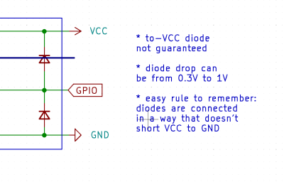 Thankfully, in modern-day Western climates and with modern tech, you are not likely to encounter ESD-caused problems, but they were way more prominent back in the day. For instance, older hackers will have stories of how FETs were more sensitive, and touching the gate pin mindlessly could kill the FET you’re working with. Now, we’ve fixed this problem, in large part because we have added ESD-protective diodes inside the active components most affected.
These diodes don’t just help against ESD – they’re a general safety measure for protecting IC and transistor pins, and they also might help avoid damaging IC pins if you mix. They also might lead to funny and unexpected results – for instance, parts of your circuit powering when you don’t expect them to! However, there’s an awesome thing that not that many hackers – they let you debug and repair your circuits in a way you might not have imagined.
Debugging Wiring And Chips Alike
Here’s a simple scenario. You have a button connected to your Arduino, with some long wires, maybe it’s even on a screwy breadboard. One pin is connected to ground, and another is connected to a GPIO. You press this button, and nothing happens in your code. Why is that?
First, you want to verify your connections, and, Arduino-internal ESD diodes let you do that with a single measurement at the button. Put your multimeter into diode test mode (or low-resistance measurement mode), then reverse your multimeter leads, putting the red lead on ground and black lead on the button pin. Then, touch the button pins and see if you can sense an internal diode – if not, your wiring is likely suspect.
This is not all, however. Do you have a broken PCIe GPU? It can be overwhelming – many things could be broken, where do you start? It could be the GPU chip itself, it could be one of the smaller memory chips, or it could be the VRM. An ESD diode test helps yet again. Put the red lead on GND, and check the card edge pins with PCIe diffpairs, probing behind series capacitors where those are present near the card edge.
The results are stunning – you can notice a GPU core chip failure that you wouldn’t normally. It’s simple – card edge-connected GPIOs will have a certain kind of voltage drop, and the PCIe link will also have a certain voltage drop, just a different one, because high-speed links need different ESD diode structures.
If one or few PCIe pins or GPIOs deviate from the PCIe or GPIO ESD diode value on all other pins, you might just have a broken core – this knowledge will save you a hefty amount of time if you are thinking of reballing the GPU or fixing some other areas like the VRM. It’s a super efficient way to test your tech, and of course, it works for other things like ICs.
There’s more – you are probing a board, and you want to know where a resistor goes. Is it a pulldown resistor, is it connected to some external connector, or is it part of some analog circuit? With red lead on ground again, check if there’s a diode – that’s how you can know it’s connected to a digital input of some sort, or floating.
Powerful, Simple, Friendly
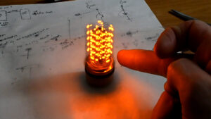
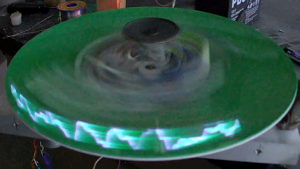
 Would you believe me if I told you there’s more? If you’ve ever browsed Aliexpress for devboards or PC tech, you have likely seen these adapters with tons of LEDs and a battery board. These are tester boards for PC components, they are beautifully analog in how they operate, and it’s insanely easy to build your own – let me show you how.
Yep, these testers also test the presence of ESD diodes. Furthermore, the LED will shine with different brightness depending on the nature of the connection. It’s seriously awesome in how quickly you can test things at a fundamental level with these boards. If your desktop’s CPU doesn’t boot, it might just be a broken ball in its LGA socket, and plugging such a tester in will save you a metric kiloton of trouble debugging other things.
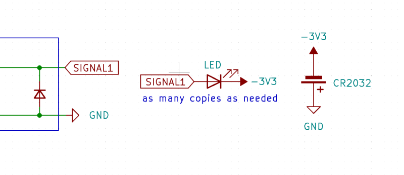
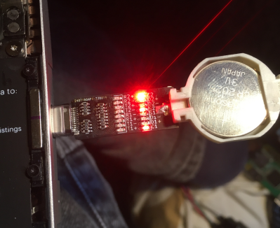
They are dead simple, too. If you want to test 20 or 200 connections at once, you only need a CR2032 battery and a bunch of LEDs – maybe some series resistors, but even those don’t seem necessary to me. The coin cell batteries have an internal resistance of their own, which helps us because we don’t need per-LED current limiting resistors – you can just shower a board in LEDs, add a coin cell holder, and make it into a debugger for anything.
As a USB-C zealot, of course, I’ve made a USB-C tester – and immediately tested it on some of my broken or mysterious USB-C ports, to great success. Here are the Kicad files, complete with a very broken-looking schematic.
For a start, this lets you check if any USB-C port you’re working with, is USB2-enabled or not. Is that docking station port “charger-only”, or can you also plug a flashdrive in? The default answer is “charger-only”, but here, you can check for sure. However, it doesn’t end here – such a tester will give you an analog-ish value the same way that a multimeter test would!
The LED brightness will vary depending on what’s connected to the pin. For instance, is this CC pin connected to an IC digital pin, is it a dead short to GND, does it just go to a pulldown resistor, or is it disconnected? This tester will show you all through LED brightness alone. It’s hard to see on the pictures, but your eye will be able to distinguish between different pins and their roles, and there’s something deeply beautiful about it.
Is your USB-C port mechanically screwy, perhaps? Or is it just that a CC pin on it is shorted, and that’s why it only works in one orientation? Maybe one of the USB3 data pairs is broken because a capacitor flew off? I’ve already managed to debug all of these cases, using this board to fix a few dead USB-C ports.
Why So Unpopular?
By now, I’m seriously confused why we never saw such a tester for, say, MicroUSB ports. How come? It’d be super easy to have LEDs for VBUS, D+, D- and ID, with the ID pin LED telling you immediately whether the MicroUSB port on your smartphone is capable of OTG mode, and it’d cost about $1. There’s no shortage of RAM and CPU testers on Eastern platforms, and repair shops have long adopted them, but the hacker world is missing out on some tiny fun peripherals that are within the reach of our fingertips.
In short, internal ESD diode testing is a severely underappreciated hacker tactic. Whatever you want to do, whether it’s PC component repair, or checking cables, or testing your boards for shorts after reflow, probing for ESD diodes is easy, and can give you insights at the speed of light.
- SEO Powered Content & PR Distribution. Get Amplified Today.
- PlatoData.Network Vertical Generative Ai. Empower Yourself. Access Here.
- PlatoAiStream. Web3 Intelligence. Knowledge Amplified. Access Here.
- PlatoESG. Carbon, CleanTech, Energy, Environment, Solar, Waste Management. Access Here.
- PlatoHealth. Biotech and Clinical Trials Intelligence. Access Here.
- Source: https://hackaday.com/2023/12/14/hacker-tactic-internal-esd-diode-probing/
- :is
- :not
- :where
- 1
- 160
- 20
- 200
- 250
- 400
- 750
- 971
- a
- Able
- About
- about IT
- active
- add
- added
- adopted
- affected
- After
- again
- against
- All
- alone
- already
- also
- amount
- an
- and
- Another
- answer
- any
- anything
- Arduino
- ARE
- areas
- At
- avoid
- back
- ball
- batteries
- battery
- BE
- beautiful
- beautifully
- because
- behind
- believe
- between
- Black
- board
- Broken
- build
- Bunch
- but
- button
- cables
- CAN
- capable
- card
- cases
- causing
- cell
- certain
- charges
- check
- checking
- chip
- Chips
- clothes
- code
- Coin
- come
- complete
- component
- components
- confused
- connected
- connection
- Connections
- controller
- Core
- Cost
- could
- course
- CPU
- Current
- damaging
- data
- day
- dead
- Default
- Depending
- Design
- deviate
- DID
- different
- digital
- disconnected
- distinguish
- do
- does
- Doesn’t
- Dont
- Drop
- due
- eastern
- easy
- Edge
- efficient
- Electronics
- encounter
- end
- error
- Errors
- Even
- EVER
- expect
- external
- eye
- Failure
- FET
- few
- Files
- fingertips
- Fix
- fixed
- floating
- For
- friction
- from
- fun
- fundamental
- funny
- Furthermore
- gate
- General
- generators
- Give
- GND
- Go
- Goes
- GPU
- grab
- great
- Ground
- hacker
- hackers
- happens
- Hard
- Have
- help
- helps
- here
- High
- holder
- How
- However
- HTTPS
- i
- ICS
- ID
- if
- imagined
- immediately
- in
- input
- inside
- insights
- instance
- internal
- into
- IT
- ITS
- itself
- jpg
- just
- Kill
- Kind
- Know
- knowledge
- known
- large
- lead
- Leads
- Led
- let
- Lets
- Level
- light
- like
- likely
- LINK
- links
- lockups
- Long
- made
- make
- managed
- many
- max-width
- maybe
- me
- measure
- measurement
- Memory
- meticulously
- metric
- might
- missing
- mix
- Mode
- Modern
- more
- most
- my
- mysterious
- Nature
- Near
- necessary
- Need
- never
- next
- no
- normally
- nothing
- Notice..
- now
- of
- off
- often
- older
- on
- once
- ONE
- only
- operate
- or
- Other
- our
- out
- overall
- overwhelming
- own
- pairs
- part
- parts
- PC
- perhaps
- peripherals
- Pictures
- pins
- Platforms
- plato
- Plato Data Intelligence
- PlatoData
- plug
- ports
- possible
- Powering
- presence
- present
- press
- Problem
- problems
- prominent
- protecting
- put
- Putting
- quickly
- RAM
- reach
- Red
- repair
- repeat
- Resistance
- Results
- reverse
- roles
- Safety
- same
- Save
- saw
- say
- scenario
- see
- seem
- seen
- sense
- sensitive
- Series
- seriously
- severely
- shine
- shops
- Short
- shortage
- Shorted
- shorts
- show
- Simple
- single
- smaller
- smartphone
- So
- some
- something
- speed
- start
- station
- Stories
- structures
- Stunning
- success
- such
- Super
- sure
- synthetic
- tech
- telling
- test
- tested
- testers
- Testing
- that
- The
- their
- Them
- then
- There.
- These
- they
- thing
- things
- Thinking
- this
- those
- Through
- time
- to
- told
- tons
- too
- touch
- touching
- trouble
- Unexpected
- until
- us
- USB-C
- using
- value
- variety
- verify
- very
- Voltage
- walking
- want
- Way..
- we
- were
- Western
- whatever
- when
- whether
- which
- why
- wide
- will
- with
- within
- working
- works
- world
- yet
- you
- Your
- zephyrnet