In the six months that have passed after the last USB-C article has been released, I have thought up a bunch of ways that these articles could have been improved. It’s, of course, normal to have such a feeling — expected, even. I now believe that there’s a few gaps that I could bridge. For instance, I have not provided enough example circuits, and sometimes one schematic can convey things better than a thousand words.
Let’s fix that! I’ll give you schematics for the kinds of USB-C devices you’re actually likely to want to build. I’ll also share a bunch of IC part numbers in this article, but I don’t have an exhaustive collection, of course – if you find more cool ICs that work for USB-C purposes and aren’t mentioned here, please do let us all know in the comments!
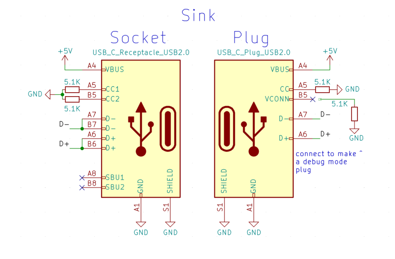
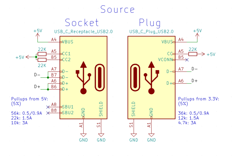
We’ve seen the first example circuit in the first article – a device-side (“upstream-facing”) USB-C port that supports USB 2.0 and 5 V of power. You must have the 5.1 K resistors, one resistor per pin, and remember to join both of the data pins — use vias if necessary. If you want to determine the amount of current available to you, you can also connect ADCs or comparators to both of the CC pins together, though most often, your device is low-power enough that there’s no reason to bother.
Now, if you want to make a device with a USB-C plug, the wiring is the same. The only difference is that you only need to populate one of the CC pull-downs, and wire up one pair of D+/D- pins instead of both pairs. Nothing bad is likely to happen in practice if you wire up the second pair of USB 2.0 pins, it’s just uncouth by the standard; it used to conflict with a certain kind of ports and cables (the VirtualLink ones) that are no longer being sold.
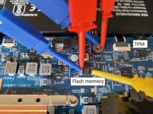
However, if you wire up 5.1 K pull-downs to both CC pins, you’ll accidentally make a hacker accessory: a debug mode adapter, something that will help you get extra signals out of some USB-C ports. For instance, on the Framework laptop, a USB-C-plug-equipped board with both pull-downs will switch a USB-C port into a debug mode, and expose the EC UART connection on the SBU pins. Unless you are making such a debug accessory, you should only populate one of the pull-downs, and wire up the USB 2.0 data pins accordingly.
The Flipside Just As Easy
What if you wanted to make a host port? From one side, it’s easier, because you don’t necessarily have to do any ADC measurements. Instead, you add pull-ups, different value for different amounts of available current. Not all devices check the pull-up presence, but phones do, so if you’re making a makeshift USB-C charger, a phone or a laptop might not recognize it as a valid way to charge if you don’t have the pull-ups. It doesn’t cost much to add them, either!
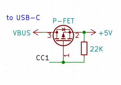
More importantly, you might want to control VBUS, only switching it on after you’ll have detected a pull-down on one of the CC pins. You won’t necessarily have a problem if you don’t, but it does cover some important edge cases, like someone plugging a USB-A to USB-C cable into your port!
I’ve never done this circuit, but the way I see it, it should be enough to use two FETs, one per CC pin, both put in parallel. This circuit might have edge cases — improvements welcome! On the other side, I’ve used pull-down-equipped USB-C port breakouts as host ports a few times, so it’s definitely not a hard requirement, and you don’t always need to break out your FET collection.
In total, there’s two things that you want to do if you’re building a host port, and neither of the two are quite required. Also, if you’d like to get more complex on the circuitry, or perhaps even do a dual-role port, there are ICs that help you with this part of USB-C!
For instance, take the WUSB3801. It takes care of both source and sink detection, has all the needed pulld-owns and pull-ups inside, and can even do dual-role ports, which lets you build any kind of 5 V power port. It can output the port status with a few GPIOs, or you can connect it to your microcontroller over I2C, and it even has an ID pin so that you can use it to fully replace a MicroUSB port with a USB-C one! The WUSB3801 is small enough, solderable enough, and versatile enough too. For instance, over on the Hackaday Discord server, someone has built a WUSB3801 circuit which limits a Li-ion charger’s current based on whether the USB-C port connected can provide 3 amps or not.
Whether you want to build a source port, a sink port, or even a port that can do both, the WUSB301 (or any of the many similar ICs like TUSB320), will be your solution of the day. One complaint I have towards the WUSB3801, is that it doesn’t provide a GPIO for determining the currently-plugged-in port polarity — you have to use the I2C interface for that. Now, why would you need to know the port polarity? High-speed interfaces are the reason, and the USB 3.0 interface is definitely a USB-C mainstay, if only because of how easy it is to implement.
High-Speed, Low-Price
Building a USB 3.0 device with a USB-C plug is as easy as building a USB 2.0 device with a USB-C plug. USB 3.0 has two high-speed diffpairs added to it, and a USB-C connector has spots for four diffpairs. With the plug, you wire up your USB 3.0 SSRX to USB-C RX1, USB 3.0 SSTX to USB-C TX1, pop a pull-down on the CC1, and you’re done. There are no extra components apart from any series capacitors that your USB 3.0 link might need, and these won’t be different from a regular implementation.
Now, this is why you will see a lot of USB flashdrives adopt a USB-C plug — it’s this easy to add one, you don’t need to figure out the CC pins, add any extra components or alike. You do need to add extra components if you aim to add a USB-C socket with USB 3.0 support, however. Imagine plugging your USB 3.0 USB-C flashdrive into a USB-C socket, depending on which way you rotate it, the pins are going to end up in one of the two positions. You don’t want to join TX/RX pins of the socket together, that would be a major signal integrity problem, so if you’re adding a USB-C socket with USB 3.0 support, you need a mux to handle high-speed signal rotation.

These are, by now, a tried and true kind of USB-C chip – you will find these from at least a dozen different manufacturers; if you find a few ICs that have the same pinout, it’ll be hard for you to get chip shortage’d. Some muxes will have a POL input, for manually switching your USB 3.0 signal into two possible positions — these are meant to be used together with your own PD controller, which is to say, a chip that handles CC pins. Many muxes, you will find, also contain CC logic, and will basically give you a complete solution for 5 V and USB 3.0 capable USB-C. If you’re building a host, you might only need to add VBUS handling, and if you’re building a device with a USB-C socket, you don’t need anything else!
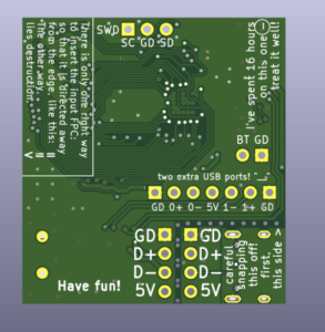
Such a mux is how a lot of cheap USB-C ports on laptops work – they only provide USB 2.0, nothing else, and given how easy it is to implement, it makes sense that a lot of cheap laptop manufacturers have stuck to this. What’s more, you could even omit the mux if you wanted if you have a USB 3.0 port to spare. We’ve seen this done on desktop motherboards, and funnily enough, this is how both of the USB-C ports are wired on the MNT Pocket Reform, too! It makes sense, the onboard USB 3.0 hub of the Pocket Reform board has four free ports, but there’s only two USB-C ports you can expose USB 3.0 on. It works well enough, and if someone wants to get at these two extra USB 3.0 ports, you only need to design a passive adapter!
One of these two USB-C ports on the Pocket Reform is special,it doesn’t just wire up the 5 V rail to VBUS like the first port does. Instead, it has a power switch IC wired up to VBUS, and a FUSB302B wired up to the CC pins. That’s the charger port of the Pocket Reform, and indeed, this is one of the ways you can get power delivery running.
Get Your Volts And Pixels
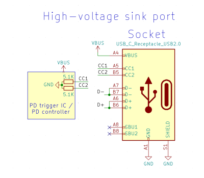 All the options we’ve talked about already support up to 15 W of power, specifically, 5 V at 3 A. Higher voltages are supported too, of course. You just need to speak PD, or perhaps, let a friendly chip speak for you.
These friendly chips, as you might guess, are PD trigger ICs. You wire them up to the CC pins, and they negotiate a power profile on your behalf. They have a few inputs that let you set the desired voltage, and optionally a FET driver output to disconnect VBUS if the PSU can’t provide the voltage you need, making sure that you don’t get the default 5 V on a power rail where you require 20 V.
We could talk a lot about the trigger chips, many other people do, and I sure have too. In fact, it’s the option that people overwhelmingly pick when they need a high voltage out of a USB-C port. They are perfect for the majority of use cases, and chances are, you want to reach for one. However, mind you, their behavior is inflexible: they won’t let you make a dual-role port, and they won’t let you distinguish between a 30 W USB-C PSU and a 100 W one, which helps when you’re driving a resistive load. You also can’t combine them with USB 3.0 or DisplayPort either as they don’t have a polarity output, and they don’t let you send custom messages.
 A PD controller will let you do way more! Whether you use an external PD controller like the FUSB302B or maybe a PD controller built into your MCU, it will let you make your own PD communication decisions. It’s got all the resistors you might want, and you’re likely to find example code for whatever task you need to accomplish. We’ve gone through custom PD message building already, both for power and DisplayPort sink operation. At some point we’ll even build our own USB-C PSU with a FUSB302B, so stay tuned! When it comes to MCUs, there are some well-known STM32 and Cypress microcontrollers with PD peripherals, and recently, the CH32X035 has entered the scene.
Your own PD controller will also let you send out DisplayPort messages — extracting a DisplayPort output from any compatible ports, or perhaps offering DisplayPort on your own. Use a USB-C plug and you will not need a mux, or use a socket and add a DisplayPort-compatible mux – it will let you extract two-lane DisplayPort and USB 3.0 simultaneously, or four-lane DisplayPort, whichever you might want. Or, you can use a DisplayPort socket, omit the mux, and only have your port work in one orientation – this Chinese eDP breakout seller can confirm!
Next time, we’ll go through the inner workings of a USB-C PSU, then convert a 20 V PSU into a USB-C source with 20 V support; we will only need the FUSB302, a few FETs, and a spare 5 V regulator. It won’t require much of us, you’ll be able to convert your old power supplies to USB-C laptop power duty, and you’ll get some insights into how a USB-C PSU operates, too!
- SEO Powered Content & PR Distribution. Get Amplified Today.
- PlatoData.Network Vertical Generative Ai. Empower Yourself. Access Here.
- PlatoAiStream. Web3 Intelligence. Knowledge Amplified. Access Here.
- PlatoESG. Automotive / EVs, Carbon, CleanTech, Energy, Environment, Solar, Waste Management. Access Here.
- BlockOffsets. Modernizing Environmental Offset Ownership. Access Here.
- Source: https://hackaday.com/2023/08/07/all-about-usb-c-example-circuits/
- :has
- :is
- :not
- :where
- $UP
- 1
- 100
- 15%
- 20
- 250
- 30
- a
- Able
- About
- accessory
- accomplish
- accordingly
- actually
- add
- added
- adding
- adopt
- After
- aim
- alike
- All
- already
- also
- always
- amount
- amounts
- AMPs
- an
- and
- any
- anything
- apart
- ARE
- article
- articles
- AS
- At
- available
- Bad
- based
- Basically
- BE
- because
- been
- behalf
- being
- believe
- Better
- between
- board
- both
- Break
- break out
- breakout
- breakouts
- BRIDGE
- build
- Building
- built
- Bunch
- but
- by
- cable
- cables
- CAN
- Can Get
- capable
- care
- cases
- certain
- chances
- charge
- cheap
- check
- chip
- Chips
- code
- collection
- combine
- comes
- Communication
- compatible
- complaint
- complete
- complex
- components
- conflict
- Connect
- connected
- connection
- control
- controller
- convert
- Cool
- Cost
- could
- course
- cover
- Current
- custom
- data
- day
- decisions
- Default
- definitely
- delivery
- Depending
- Design
- desired
- desktop
- detected
- Detection
- Determine
- determining
- device
- Devices
- difference
- different
- discord
- distinguish
- do
- does
- Doesn’t
- done
- Dont
- dozen
- driver
- driving
- easier
- easy
- EC
- Edge
- either
- else
- end
- enough
- entered
- Even
- example
- expected
- external
- extra
- extract
- fact
- FET
- few
- Figure
- Find
- First
- Fix
- flipside
- For
- four
- FRAME
- Framework
- Free
- friendly
- from
- fully
- gaps
- get
- Give
- given
- Go
- going
- gone
- hacker
- handle
- Handles
- Handling
- happen
- Hard
- Have
- help
- helps
- here
- High
- higher
- host
- How
- However
- HTML
- http
- HTTPS
- Hub
- i
- I’LL
- i2c
- ICS
- ID
- if
- imagine
- implement
- implementation
- important
- improved
- improvements
- in
- input
- inputs
- inside
- insights
- instance
- instead
- integrity
- Interface
- interfaces
- into
- IT
- join
- just
- Kind
- Know
- laptop
- laptops
- Last
- least
- Lets
- like
- likely
- limits
- LINK
- load
- logic
- longer
- Lot
- major
- Majority
- make
- MAKES
- Making
- manually
- Manufacturers
- many
- max
- max-width
- maybe
- MCU
- meant
- measurements
- mentioned
- message
- messages
- might
- mind
- Mode
- months
- more
- most
- much
- must
- necessarily
- necessary
- Need
- needed
- Neither
- never
- no
- normal
- nothing
- now
- numbers
- of
- offering
- often
- Old
- on
- Onboard
- ONE
- ones
- only
- operates
- operation
- Option
- Options
- or
- Other
- our
- out
- output
- over
- overwhelmingly
- own
- pair
- pairs
- Parallel
- part
- passed
- passive
- People
- per
- perfect
- perhaps
- peripherals
- phone
- phones
- pick
- pins
- plato
- Plato Data Intelligence
- PlatoData
- please
- plug
- Point
- pop
- ports
- positions
- possible
- power
- practice
- presence
- Problem
- Profile
- provide
- provided
- purposes
- put
- Rail
- reach
- reason
- recently
- recognize
- reform
- regular
- regulator
- released
- remember
- repeat
- replace
- require
- required
- requirement
- running
- same
- say
- scene
- Second
- see
- seen
- send
- sense
- Series
- set
- Share
- should
- side
- Signal
- signals
- similar
- simultaneously
- SIX
- Six months
- small
- So
- sold
- solution
- some
- Someone
- something
- Source
- speak
- special
- specifically
- standard
- Status
- stay
- STM32
- such
- support
- Supported
- Supports
- sure
- Switch
- takes
- Talk
- Task
- than
- that
- The
- their
- Them
- then
- There.
- These
- they
- things
- this
- though?
- thought
- Through
- time
- times
- to
- together
- too
- Total
- towards
- tried
- trigger
- true
- two
- us
- usb
- USB-C
- use
- used
- value
- versatile
- Voltage
- W
- want
- wanted
- wants
- Way..
- ways
- we
- WELL
- well-known
- whatever
- when
- whether
- which
- why
- will
- Wire
- with
- words
- Work
- workings
- works
- would
- you
- Your
- zephyrnet